Schematic diagram of energy storage batt ontrol unit called battery management system (BMS). Figure 1 below presents the block diagram structure of BESS. Capacity[Ah]: The amount of electric charge the system can deliver to the conne ted load while maintaining acceptable volt the caveats to consider in their development. Energy-related carbon dioxide emissions. . e need for innovative energy storage solutions. Battery Energy Storage System (BESS) has been an integral part of energy generati n, transmission, distribution, and consumption. en renewable energy (such as solar energy and wind energy) and power grid. As the global demand f r clean energy increases,the. .
[pdf] Energy storage liquid cooling systems generally consist of a battery pack liquid cooling system and an external liquid cooling system. The core components include water pumps, compressors, heat exchangers, etc. Thermal behavior in battery energy storage systems is tightly coupled to electrochemical. . Today, the two dominant thermal management technologies in the battery energy storage industry are air cooling and liquid cooling. These are not simply generational upgrades of one another, but rather two optimized solutions tailored for different climates, operational conditions, and project. . Discover how advanced liquid cooling technology optimizes thermal management in industrial and renewable energy storage systems.
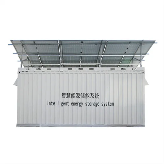
[pdf] For EPC contractors, OEM distributors, and industrial energy service providers, adopting liquid cooling solutions enables them to offer scalable, safe, and efficient energy storage systems that meet the rising demand for renewable energy storage. · Intrinsically Safe with Multi-level Electrical and Fire Protection. · Premium Grade A. . Energy storage cabinets play a vital role in modern energy management, ensuring efficiency and reliability in power systems. This guide explores the benefits. . Project features 5 units of HyperStrong's liquid-cooling outdoor cabinets in a 500kW/1164. 8kWh energy storage power station.
[pdf] In this article, we are going to learn how the EV charging system works with a detailed block diagram. This block diagram simplifies the complex design and working concept so we can understand it very easily. Click on the Image to Enlarge. An Electric Vehicle (EV) charging station supplies power for recharging electric vehicles. The smart controller manages security, services and connectivity to a remote server and the power. . To address interaction challenges among the power grid, EVs, and energy storage batteries, a distributed energy storage-integrated bidirectional converter topology for EV charging piles is proposed. Fast-charging electric vehicles requires a sufficiently powerful connection to the electric power grid. Understanding it can help you make the best decisions when. .
[pdf] Three diagrams with photovoltaics and energy storage – Hybrid, Off Grid, Grid-Tied with Batteries. In this article, you will find the three most common solar PV power systems for domestic and commercial use. DC-DC converter and solar are connected on common DC bus on the PCS. Energy Management System or EMS is responsible to provide seamless integration of DC coupled energy storage and solar. . A solar energy storage system diagram is the foundational roadmap for any successful solar power installation. It's more than just a drawing; it is a detailed plan that illustrates how every component connects and interacts to generate, store, and deliver power. Sometimes two is better than one. However, the intermittent and unstable nature of. .
[pdf]